![]()
Section
3
Invention No. 2:
A
New Isentropic Cone Motor Apparatus for Amplifying and Extracting Power from
Wind and Moving Air
Abstract: Regular windmills
are limited in power output by the available wind speed. The wind speed cannot
be changed, while intercepting a larger
mass of air to increase the power requires large and expensive propellers. Here
we describe a new air motor, called a cone motor, which greatly increases the
speed of the wind through the apparatus and so enormously increase its power
output at very low cost.
Contents
3.1 An Isentropic Method
for Greatly Increasing and Extracting
Power from Moving Air
3.2 Invention No. 2: A Cone Motor Method and Apparatus
BACKGROUND TO THE INVENTION
BRIEF SUMMARY OF THE INVENTION
BRIEF DESCRIPTION
OF THE DRAWING
DETAULED DESCRIPTION
OF THE INVENTION IN A PREFERRED EMBODIMENT
Nozzle Design Details
Power-take
off Means
Design Details and Procedures
Application to Providing Greatly Increased Air Power on Moving Vehicles
Design Safety Considerations: Rotor
Mechanical Strength and Noise Hazard
Design Steps
References
3.1 An Isentropic Method for Greatly
Inceasing and Extracting Power
from Moving Air
The
amount of additional internal flow power added in isentropic acceleration is
truly astonishing. The power in an air flow in a duct can be computed [1] by the formula:
P = ½ (ρVA) V2
(1)
where
ρ is the air density, V is its velocity and A is the cross-sectional area of the
intercepted air flow.
For
a windmill, having a propeller
diameter D = 2R, this becomes the engineering formula
P = ½ ρ ( πR2) V3 = ½ ρ ( πD2 /4) V3
(2)
If ρ, V, A and R are in SI units ( kilogram, meter, second)
then the power P in Equations 1 and 2 will be in watts.
Noting
that ρVA is the mass rate of
flow (m-dot = dm/dt = ρVA),
where m-dot is in kilograms per second, we can rewrite power Equation 1 as
P = ½ (m-dot) V2
(3)
From
this we see that if the mass rate of flow is employed, then the power that can
be obtained from a windmill is equal to the product of the mass rate of flow
and the average wind velocity squared. In practice, since the average wind
speed at a particular site is a given and uncontrollable quantity, this means
that we can only increase a windmill’s power by increasing the mass flow rate
and that requires intercepting a larger mass of air, which in turn means using
larger diameter windmill propellers, making the present windmills very expensive
for reasonably large power outputs.
From
these power formulae we can now see how remarkable is the power amplification
available from the acceleration of an air flow as in the invention to be
described. For example, for a wind flow
of 5 m/s and a propeller diameter of 0.1 m, the power in the natural wind flow is
P = ½ (ρVA) V2
(1)
P = ½ x 1.2 x 5
x 0.1 x 25 = 7.5 watts.
But,
if the same air stream is accelerated in a converging nozzle, then at the
throat at sonic speed of 313 m/s, the power of the same air stream becomes:
P =
½ x 1,2 x .63394 x 0 .1 x 3132 = 3626 watts, or an increase of 483
times!
3.2 Invention No. 2: A Cone Motor Method and Apparatus
Using the flow principles
set out in some detail in Parts I and II, the new invention is presented in
excerpts from the Patent Application as follows:
“An Isentropic Method and
Apparatus for Greatly Increasing and
Extracting the Power from Wind and Moving Air”
BACKGROUND TO THE INVENTION
 0002.
The extraction of useful power from the wind is increasingly important to a
world in need of economical, renewable, clean and environmentally “friendly” energy
sources. Still, the economics and efficiencies of the windmill art remain
deficient or have reached various limits. Wind
power is at the present time still relatively expensive because of the
high cost of the large propellers and large supporting structures required to
produce reasonably large amounts of power, while at the same time the low wind strengths and variability of the wind energy input have been beyond human control.
0002.
The extraction of useful power from the wind is increasingly important to a
world in need of economical, renewable, clean and environmentally “friendly” energy
sources. Still, the economics and efficiencies of the windmill art remain
deficient or have reached various limits. Wind
power is at the present time still relatively expensive because of the
high cost of the large propellers and large supporting structures required to
produce reasonably large amounts of power, while at the same time the low wind strengths and variability of the wind energy input have been beyond human control.
0003. Setting up an air flow so as to then use its kinetic energy to do useful work is commonly done by using either a vacuum or “pull flow” source, or by a using a compression or “ push flow” source. Here I disclose a new method and apparatus for a vacuum flow air energy source that uses the atmospheric wind ts basic mass flow source, and moreover does so in a novel and far more efficient manner than existing prior art.
0004. The power in the wind approaching a windmill can be computed [Ref.1] by the formula:
P = ½ (ρVA) V2 (1)
where ρ is the air density, V is its velocity and A is the cross-sectional area of the intercepted air flow.
For a windmill, having a propeller diameter D = 2R, this becomes the engineering formula
P = ½ ρ ( πR2) V3 = ½ ρ ( πD2 /4) V3 (2)
If ρ, V, A and R are in SI units ( kilogram, meter, second) then the power P in Equations 1 and 2 will be in watts.
Noting that ρVA is the mass rate of flow (m-dot = dm/dt = ρVA) where m-dot is in kilograms per second, we can rewrite the power equation 1 as
P = ½ (m-dot) V2 (3)
From this we see that if the mass rate of flow is employed then the power that can be obtained from a windmill is equal to the product of the mass rate of flow and the average wind velocity squared. In practice, since the average wind speed at a particular site is a given and uncontrollable quantity, this means that we can only increase a windmill’s power by increasing the mass flow rate and that requires intercepting a larger and larger mass of air, which in turn means using larger and larger diameters for the windmill propellers, making the present windmills very expensive for reasonably large power outputs.
0005. Currently, the cost of production of power from the wind is higher than hydroelectric power, nuclear power or power from fossil-fuel fired gas turbines.
0006. To repeat, the two current major limiting factors in wind power production are, first, the large and costly propellers and associated large support structures to intercept a reasonably large mass flow of air, and, second, the generally low average wind speeds prevailing at most accessible windmill sites, and therefore the low kinetic energy of air flow available to the windmill propeller blades.
BRIEF SUMMARY OF THE INVENTION
0007.
In the present invention, I disclose a method for greatly accelerating the air
flow through the apparatus, and thereby
greatly increasing the available
kinetic energy of flow and the power available for useful work. This increase of power is
accomplished by an isentropic acceleration [Ref. 2, 3, 4] of the air flow.
0008. My invention employs the basis mass flow of air set up by the wind, and then greatly increases its kinetic energy. Since a basic ingredient is a moving stream of air, the invention applies also to an embodiment in which the basic moving stream of air is supplied by, say, the relative air flow past a moving vehicular platform, such as an automobile, train, ship or airplane, etc,. on which the invention apparatus is mounted. Ina preferred embodiment, my invention employs converging and diverging nozzles to accelerate and then decelerate the air flow efficiently, such a system being commonly described as a De Laval Nozzle.
0009. The invention will now be briefly described in a preferred embodiment as follows: An apparatus for greatly increasing the power of a flow of air from the wind consisting of a De Laval Nozzle, said nozzle having an inlet converging cone and an exit diverging cone attached together at their minimum cross-sections to form said De Laval Nozzle’s throat section, said nozzle being kept pointed into the wind or air flow by a vane or other orienting means, said air flow setting up a fixed mass flow of air through said De Laval Nozzle, which mass flow is proportional to the prevailing average wind speed; said flow of air through said nozzle increasing in speed through said converging nozzle section to reach near sonic speed of 313 m/s in said nozzle’s minimum or throat section, said sonic flow then decelerating efficiently and isentropically in said diverging cone section to reach ambient wind speed and pressure at the said diverging nozzle exit Said increased air flow power being accessed or tapped into immediately downstream of said nozzle’s throat section by a flow port leading to a rotating power take-off means.
BRIEF DESCRIPTION
OF THE DRAWING
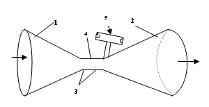
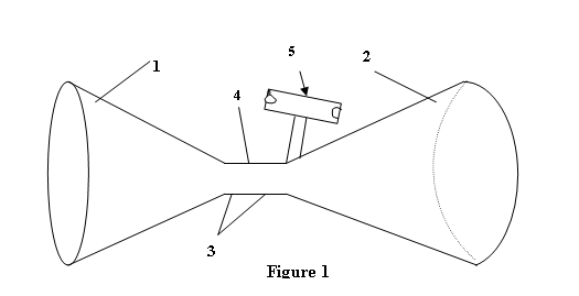 0010.
Figure 1 shows the an embodiment of the apparatus
, consisting of converging and diverging cones 1 and 2 of a De Laval
Nozzle, said cones being connected
together to form a nozzle throat 3, said
throat having a bleed port or power take-off
access port 4 connected to a
rotating power take- off means 5. The flow
power port 4 immediately downstream of the throat 3
of the De Laval Nozzle allows
access to the low pressure area in the
nozzle throat 3; the pressure gradient
between said low pressure in the throat area and the ambient pressure in the
inlet to the power take-off means 5, draws
air in through a rotor of said power
take-off means, the air
0010.
Figure 1 shows the an embodiment of the apparatus
, consisting of converging and diverging cones 1 and 2 of a De Laval
Nozzle, said cones being connected
together to form a nozzle throat 3, said
throat having a bleed port or power take-off
access port 4 connected to a
rotating power take- off means 5. The flow
power port 4 immediately downstream of the throat 3
of the De Laval Nozzle allows
access to the low pressure area in the
nozzle throat 3; the pressure gradient
between said low pressure in the throat area and the ambient pressure in the
inlet to the power take-off means 5, draws
air in through a rotor of said power
take-off means, the air
accelerates in said rotor and the reaction force to the acceleration rotates said rotor for doing useful work.
DETAILED DESCRIPTION OF THE INVENTION IN A PREFERRED
EMBODIMENT
0011. In my invention, the current disadvantages of conventional windmill low power production from low wind speeds are overcome in an entirely novel manner. I first pass a mass flow of air powered by the wind through a properly designed De Laval Nozzle [Ref. 3,4] ]. The mass flow of air is first accelerated in the converging or entry conical section of the nozzle efficiently and isentropically to near sonic speed at the nozzle throat section; it is then decelerated efficiently and isentropically through the diverging or exit nozzle back down to ambient wind speed and up to ambient air pressure at the nozzle exit. I then extract a portion of the vastly increased flow energy and power immediately downstream of the nozzle throat by a rotating power take-off means to do useful work.
0012. It is pointed out that in any air flow apparatus the two basic physical elements are, first, the mass flow of air through the apparatus that sustains the flow speed and power and, second, the pressure differential between entrance and exit to the apparatus that initiates and sustains the mass flow. The pressure differential is the difference in static pressure between the entrance to the apparatus and the exit from the device; it does not concern any of the various pressure differences which may occur within the flow device after entrance and before exit. For low air speeds (less than about Mach 0.3) the Bernoulli equation for incompressible flow will suffice to determine the pressure differential and flow velocities. For higher speeds, the isentropic flow relations must be used. These various flow equations will all be discussed later in this specification.
 0013. The main elements in my invention can be conveniently discussed under four
headings or groups. First, there is a basic mass flow of
air supplied by the wind, second, the
velocity of this basic mass flow is greatly accelerated efficiently to near
sonic speed at the nozzle’s narrowest cross-sectional area or “throat” to increase its kinetic energy and
power, third, the higher speed flow is
then decelerated efficiently back down
to lower speed and exit ambient
pressure to preserve the basic mass flow through the apparatus, and fourth the increased energy and power
associated with the high speed flow at the throat is efficiently used by a rotating
power take-off means attached immediately downstream of the nozzle
throat by a vacuum pressure take- off port to do useful work. We now examine each of these elements in
turn.
0013. The main elements in my invention can be conveniently discussed under four
headings or groups. First, there is a basic mass flow of
air supplied by the wind, second, the
velocity of this basic mass flow is greatly accelerated efficiently to near
sonic speed at the nozzle’s narrowest cross-sectional area or “throat” to increase its kinetic energy and
power, third, the higher speed flow is
then decelerated efficiently back down
to lower speed and exit ambient
pressure to preserve the basic mass flow through the apparatus, and fourth the increased energy and power
associated with the high speed flow at the throat is efficiently used by a rotating
power take-off means attached immediately downstream of the nozzle
throat by a vacuum pressure take- off port to do useful work. We now examine each of these elements in
turn.
0014. (1). The first element of the present invention, the basic mass flow, is supplied by the wind or by a relative flow of air moving past a vehicular platform upon which the apparatus of the invention is mounted. The mass flow has following formula:
ρ1 V1 A1 = ρ2 V2 A2 = dm/dt = m-dot = constant
0015. A basic mass flow may be set up in a fluid in several ways: first, a vacuum source may be used to “pull” the air through the apparatus, second, an air compressor maybe used to “push” the air flow through the apparatus, third, as in the present invention, an air flow such as the wind or the air blowing past a moving vehicle may be entrained into and through the apparatus.
0016. In connection with maintaining a given mass flow, it will be well to point out that any flow of air from whatever source through an apparatus will involve the pressure difference across the apparatus from inlet to outlet; it is this pressure difference which drives and maintains the mass flow. In the case of a vacuum pump flow source, the pressure difference will be that between the ambient pressure at the inlet to the apparatus and the vacuum pressure maintained at the vacuum pump. In the case of a compressor, it will be the difference between the compressor exit pressure and the ambient pressure at the apparatus flow exit port. In the case where the source of the mass flow is the wind, the pressure differences across the apparatus from entrance to exit are very much smaller, being just the dynamic or flow pressure of the air, p = 1/2 ρ V2. For example, a wind speed of 10 m/s will have a dynamic pressure of p = ½ x 1.2 x 102 = 60 Pascals or 0.6 millibars. This is therefore the pressure differential across the apparatus from entrance port to exit port in a wind of 10 m/s that must be maintained in order to maintain the mass flow through the apparatus. Inefficiencies in the flow through the apparatus such as turbulence and friction will lower the flow speed, pressure differential, mass flow and power of the flow through the apparatus.
0017. Since the wind pressure differences are relatively small, care must be taken to ensure that the De Laval nozzles employed to accelerate the flow also decelerate the exiting air flow through the diverging section to the atmosphere properly and efficiently without significant turbulence or other heat energy dissipation losses i.e. to return the air to the ambient atmospheric pressure, temperature and wind speed prevailing at the nozzle exit, otherwise mass flow will drop and power will be lost.
0018. (2) The second element of the invention , namely that of accelerating the mass air flow to high speeds near the sonic limit at the nozzle throat, can be achieved by decreasing the cross-sectional area of the flow duct as in the converging section of a De Laval nozzle. This flow accelerating process is an isentropic one with no heat flowing into or out of the mass air flow [ Ref. 2,3,4].
0019. (3) The third element in the invention, namely that of decelerating the high speed, low pressure air at the throat of the nozzle back to low speed and ambient pressure at the apparatus flow exit port , is accomplished in the De Laval nozzle’s diverging section as is well known to those versed in the art. This deceleration flow process is also an isentropic one, and is more difficult to achieve efficiently , that is without losses, than the acceleration process [Ref. 2].
0020. (4) The fourth element in the invention, namely the efficient extraction of the increased airflow kinetic energy and power may be achieved in various ways, such as for example with an air turbine, a propeller, and so on. In a preferred embodiment of this invention to be described below, the power is extracted by a reaction rotor [Ref. 5] in which the low pressure at the De Laval Nozzle throat is used to draw in a mass flow of air through the power take-off rotor, accelerate it to sonic speed and use the acceleration thrust forces to rotate the rotor and do useful work.
To take a specific example, consider a steady wind flow of 1 m/s entering a nozzle having an inlet area of 1 sq. meter. With the air density being about 1.2 kg. per cubic meter at sea level, we would then have from Equation 6 a mass flow rate of ρ1 V1 A1 = 1.2 x 1 x 1 = 1.2 kilograms per second, minus any entrance lip losses.
If this mass flow, for example, is passed through a De Laval Nozzle, then at the minimum cross-sectional area or ‘throat’ of the nozzle, the flow speed will have been accelerated to sonic speed, that is to say to 313 m/s. The throat air power then is
P = ½ m-dot 3132 = ½ x 1.2 x 3132 = 58781.4 watts = 58.8 kw
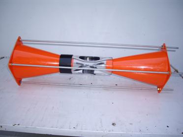
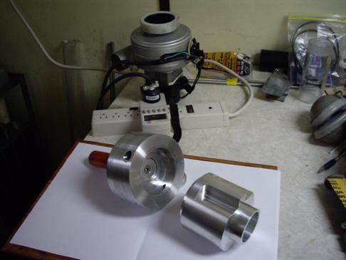
Cone Accelerator
Assembly without Power Take-off Rotor
Nozzle Design Details
0029.
In the case where the mass inflow is powered by the wind, there may also be
back pressure losses set up at the exit to the atmosphere if the accelerated
sonic flow at the nozzle throat is
decelerated inefficiently back down to
ambient wind speed. values at the nozzle exit.
Such back pressure losses have
the effect of reducing the pressure gradient through the nozzle between
entrance and exit, thus reducing the
flow speed, mass flow and the
air power at the throat which is connected to the power take-off means. These losses must be properly reduced in the design for
maximum power output. This is
accomplished by a nozzle design in which I add
a diverging cone at the
throat exit to further channel the exiting
flow immediately it leaves the high flow speed area at the throat of the converging nozzle.. The throat high speed flow is thereby
decelerated smoothly and efficiently
through the diverging section without inefficient energy
losses to friction, turbulence or heat so that the flow recovers from its low pressure/high velocity
values at the throat towards the
atmospheric pressure and low ambient wind speed values which it must match at
the duct exit to avoid the back pressure losses and so to maintain the basic
mass flow.
0030. To design an efficient means for using the method of my invention in a particular case, the designer has several options. He can, for instance, first choose the amount of throat air power( that is, the vacuum pressure drop at the throat) that he wishes to produce to feed to the power-take off means. This in turn sets the necessary size of the throat area of the converging cone A*. needed to pass the mass flow through the throat at sonic speed to produce the throat power, which in turn sets the inlet converging nozzle diameter needed, for the prevailing average wind speed inlet flow, to deliver that mass flow rate.
0031. An example may help to clarify the design procedure: First, select a desired throat air flow power, say, 48,984.5 watts. Then, the mass flow matching this at sonic speed is obtained from Equation 3 , P = 48,984.5 = ½ x m-dot x 3132, so that m-dot, the mass flow rate equals 1 kg/s. Then from Table 1 we see that a flow of 1 kg/s at sonic speed requires a throat diameter of 0.073 meters. Then we need a wind speed that will deliver 1 kg/s through a converging nozzle. Clearly, this will depend on the wind speed prevailing. For example, an average wind of 1 m/s through a cone with an inlet area of 1 square meter would deliver 1 cubic meter of air per second, and this, with an air density of 1.2 kg per cubic meter, would deliver a flow of 1.2 kg/s. Therefore a 1 kg/s flow would need a wind of 1/1.2 = 0.83 m/s. Again for a wind speed of 5 m/s the mass flow of 1 kg/s will require a nozzle having an inlet area of 1/5 x 0.83 = 0.166 sq. m . Or, an average wind speed of 10 m/s would need one tenth of a square meter inlet area times 0.83 or 0.083 sq. m. to maintain the selected mass flow of 1 kg/s.. Since the wind speed is never constant we see that some variation in actual mass flow and throat power will be inevitable.
0032. The designer could of course also proceed by first choosing, say, the throat diameter instead of the throat air power, for example a diameter of 0.073 m.. This at once sets the throat mass flow from the equation of continuity at:
m- dot = ρ*V*A* = [1.2 x .063394 x π x (0.073/2)2 = 1 kg/s as before.
and the throat air power at sonic speed is again
P = ½ x m-dot x 3132 = ½ x ρ*V*A* = 48,984.5 watts
Then, as before, the mass flow sets the inlet cone diameter from the average wind speed and the equation of mass continuity.
0033. Then, for any wind V1 bringing in a mass flow (ρVA)1 through the converging cone of 1 kg/s, a throat air flow power of 48.9845 kw will be produced at sonic speed. Less wind input will produce less power; a higher average wind than the selected design speed will exceed the design mass flow rate that can be passed through the throat and the flow will ‘choke’ or stop increasing, and the throat air power will remain constant at 48.984 kw.
0034. To design for a higher average input wind speed V1 , the designer will need to increase the throat area A* to accommodate the higher average mass flow rate m-dot = ρ1 V1 A1; this increase in mass flow rate will then increase the output power available. The flow rate can also be increased by increasing the size of the inlet area A1, and this will then also require an increase in the throat area A* to accommodate the increased mass flow rate; other design options can be worked out in similar fashion. The proper design procedures and dimensions for the diverging section of the flow system for each case will be well known to those versed in the art of De Laval nozzle design.
0035. It is, of course, not necessary to let the flow increase to its maximum or sonic speed of 313 m/s, and, if desired, the nozzle can be designed to run at any smaller throat speed. Finally, if the nozzle is designed to pass a mass flow which is less than the flow that the prevailing average wind speed offers for entry to the nozzle for that particular wind speed and nozzle inlet area, then the flow will “choke” or remain constant at the design mass flow rate value. The invention can be operated in this mode if desired, or, as we shall see later, it can be operated so that the vacuum drop available is bled off at the throat and used to induce a subsidiary flow whose energy can be tapped and used in the rotating power take-off means.
0036. Tabulations of isentropic flow values of pressure, temperature, density versus flow Mach number are readily available [Ref. 2, 3] for computations of the isentropic values used in nozzle design. However, the exact isentropic equations for nozzle design are most easily applied by one of various commercially available nozzle design computer programs.
0037. It is also pointed out that,
while in this disclosure I have
mentioned conical nozzles, that other nozzle shapes, such as parabolic
converging and diverging nozzle sections, or
0038. I also point out that all of the throat power is obviously not available for power take-off, since the basic mass flow of air must be maintained through the throat to in turn maintain the sonic speed and energy. The power take-off means will next be described.
Power Take-off
Means
0039.The fourth element in the invention is the power take-off means for efficiently extracting the high speed flow energy and high power immediately downstream of the nozzle throat to do useful work while maintaining the basic mass flow intact. In the present invention this is done by using the vacuum or ‘suction’ at the throat, which is generated by accelerating the flow, in a novel way.
0040. In the prior art on windmills, a propeller, or flow turbine is positioned directly into the wind flow to extract its low speed power. There is then a deceleration of the wind flow through the propeller, or turbine which results in rotation being imparted to them. The Betz Limit [Ref. 1] sets 59.2% as the maximum power that can be extracted from the air by such means. In practice there are also other flow energy losses so that net efficiency of power extraction is typically from 30 to 40%.
0041. In my invention, I first accelerate the wind or air flow many times over at the throat of a De Laval nozzle assembly. However, if one were to employ the same methods of extraction as in an ordinary windmill by inserting a propeller or turbine directly into the accelerated air flow, one would greatly disturb the isentropic flow and reduce the mass flow and the flow power. But, I much more efficiently employ another means of extracting the high speed flow power generated at the nozzle throat, that avoids disrupting the flow. In my method, I insert a power take- off port or ports immediately downstream of the nozzle throat which, when connected to a rotating power take-ff means [Ref. 5], efficiently extract a substantial portion of the throat air flow power without reducing the mass flow below the design value. The vacuum pressure gradient set up between the low pressure in the throat flow ( approx 47.5 kPa ) and the outside ambient atmospheric pressure ( approx. 100 kPa ) at the entrance to the take-off port, provides the vacuum pressure gradient or ‘suction’ to set up a subsidiary mass flow of air in though the power take-off rotor. of the apparatus . (At sonic speeds this pressure drop or take-off ‘suction’ is about one half an atmosphere (i.e. 100 – 47.5 = 52.5 kPa.).
0042. To see this more clearly the tabulations of Tables 2 to 4 have been prepared :
Table 2
Air Power from a Conventional Windmill and
the Present Invention Compared
(For a fixed mass flow of 1 kg/s)
Wind Speed (m/s) Windmill Air Power (1) Invention’s Throat (Sonic) Power (2)
1 0.6 watts 48,945 watts
5 12.5 watts 48,945 watts
10 50 watts 48,945 watts
20 200 watts 48,945 watts
Notes:
(1) P = ½ x m-dot x V2; (2) P = ½ x m-dot x 3132
(3) We see that the power is produced by the product of the mass flow and the square of the wind speed through the turbine. The basic mass flow is indeed the same with a windmill and with my invention, but the flow speeds through my invention at the nozzle throat section are many times larger than the wind through a conventional windmill and so the flow power available at the throat is enormously increased. (For a fixed mass flow, the power is proportional to the flow velocity squared).
Table 3
Nozzle Dimensions , Potential Throat Air
Power (1) and Choked Air Power (2)
Wind Speed 5 m/s 10 m/s 15 m/s 20 m/s 25 m/s
Cone Inlet diameter 46 cm 32.6cm 26/6 cm 23cm 20.6cm
Potential Mass Flow 1 kg/s 2 kg/s 3 kg/s 4 kg/s 5 kg/s
Throat Power (1) 49 kw 98 kw 147 kw 196 kw 245 kw
Choked Power (2) 49 kw 49kw 49kw 49kw 49kw
Notes:
1. Throat Air Power is the power at sonic throat speed when the throat diameter is matched. to accept and pass the mass flow rate available from the wind ( P = ½ x mass flow rate x 3132 )
2. Choked power is the Throat Power if throat diameter is held at, say for example, 7.31 cm which can only pass 1 kg/s; .therefore for wind speeds greater than 5 m/s, this diameter of 7.31 cm ‘chokes’ or holds the flow constant at 1 kg/s and the power constant at 49 kw. even although the wind speed is great enough to produce increased power. To tap the greater power available with increased wind speed, we can simply enlarge the throat diameter at the take-of port to accept and pass the increased mass flow available from the increased wind speed.(See Table 2).
Table 4
Mass Flow Rate and Matching
Minimum Nozzle Throat Diameter Needed to Pass It at Sonic Speed
Mass
Flow Rate Matching Throat
Diameter Sonic Throat Air Power
1 kg/s 7.31 cm 49 kw
2 10.3 “ 98
3 12.7 “ 147
4 14.6 “ 196
5 16.4 “ 245
0043. The invention makes an enormous improvement in potential power output versus the prior windmill art. In the prior art, the wind flow power is set by the mass flow and the input wind speed squared. For example, a wind of 5 m/s and a mass flow of 1 kg/s will have an air power of P = ½ x 1 x 52 = 12.5 watts . In contrast, in my invention, the input wind speed is greatly accelerated by the converging cone at the throat and will now have a throat flow speed of 313 m/s instead of the wind speed which is typically around 10 m’s on the average. The apparatus in my invention will now have a throat power of ½ x 1 x 3132 = 48,985 watts, which is 3919 times larger than the windmill prior art air power as can be seen from Table 2.
0044. Of course , the throat power is not the actual power that can be extracted by the power take-off means. The extractable power in the present invention has two components. First, only a fraction of the throat power can be bled off at the vacuum pressure take-off ports if the throat mass flow rate is to be kept at or above the sonic flow speed mass flow rate value; the amount of the bleed-off will depend on the “overdesign” value chosen, as described above. Second, the bleed-off vacuum mass flow can not all be converted into usable rotational power by any take- off means. In the case of a windmill propeller take-off, the absolute limit is 59.2% of the flow through the propeller ( i.e.the Betz Limit).
In the case of the rotor take-off means of the preferred embodiment described in the present application ( Ref. 5) the take-off power percentage is 50% . However, in the present invention the final take-off power is still hundreds of times larger than the power available from a prior art windmill oafm the same diameter under thee same input wind speed and mass flow condition.
Power Take-off Section of Isentropic Air Motor Showing (left to right) 4-Nozzle Rotor, Vacuum Line
Coupler
Design Details
and Procedures
0045. To design for a given desired Power and Average Wind Speed. The central fact to note here is that any power take-off will affect the mass flow through the inlet cone, since the flow will partition in proportion to the ratio of the areas of the inlet duct and the power take-off port. In practice it is found easiest to work with and compare the throat areas. If they are equal then they will pass the same flow and the mass flow will partition equally between them.. If they are different, the .flow will partition in proportion to their area ratio. Therefore, if we open a pressure bleed or take-off port just downstream of the throat and it has the same area as the main nozzle throat then the flow will- if it is nowhere choked - partition equally between the two openings. That is to say, the mass flow through each separate inlet opening, will be one half of the total mass flow passing through the apparatus.
0046. If the flow is choked at the throat section in any duct, the situation is different. Suppose the main cone inlet has its throat area so small that it chokes the flow there. This fixes the total mass flow it can pass. If then a bleed port is opened mass will flow through the bleed port in proportion to the ratio of the two throat areas so long as the flow remains constant at tht choked value in the main cone duct. This suggests a design strategy as follows: We “over-design” the main conical duct so that the flow is choked several times over at the throat; this is done by simply making the cone inlet area larger than needed to pass the prevailing wind flow through the throat, thus more mass flow is available than can pass and the flow remains choked, and the throat pressure remains at sonic value even when bleed air is admitted from the power take-off rotor through the bleed port. This can continue until more bleed air is admitted than the choking condition will sustain, at which point the throat flow will drop below sonic speed, the throat pressure will begin to rise, the available vacuum ‘suction’ will drop, and the power take-off limit has been reached.
0047. For example, suppose we wish a net power output of 49 kw for a site with an average wind speed of 5 m/s. Assuming an efficiency of power take-off of 50% , we would then need to design for double the power to compensate for the take-off losses. But if we were to design for that exact value then when we do take off any power the throat speed of the mass flow will drop below sonic and the power will drop.
0048. So, to compensate for this, we “over-design” as follows: We take, for example, 4 x 49 -= 196 kw as the available wind power needed at the throat. Then from Table 4 we see that this will require a mass flow of 4 kg/s and for a site with an average wind of 5 m/s this will require an inlet cone with inlet diameter of 0..65m. But we actually keep the throat size at only 0.7321 m which will only pass 49 kw. This means that under average wind speeds the nozzle will have a potential for 196 kw but the flow will “ choke” and the apparatus will only actually pass 49 kw through the throat. However, if we now draw off flow and power from the choked power at the throat, we will still have lots of power in reserve and so will continue to have sonic speed and 49 kw at the throat while we take off 49 kw of power to the outside for useful work, since we have over-designed to allow for 50% loss. . This cone design will deliver 49 kw of take off power and the flow will have enough built in reserve of potential mass flow that the flow will still remain sonic at the throat while the power is taken off. See Tables 3 and 4 above, and Table 5 below.
Table
5
Mass Flow and Air Power versus Cone
Inlet Diameter
Mass flow Throat Size Air Power Cone Inlet Diameter at Various Wind Speeds
5
m/s 10mm/s 20 m/s
1 kg/s 0.731 m 49 kw 0.46 m 0.33 m 0.23 m
2 98 0.64 0.46 0.33
3 147 0.80 0.56 0.40
4 196 0.92 0.65 0.46
5 245 1.03 0.73 0.51
0049. In the case of a conventional wind mill, if we should want to design for four times the power we must quadruple the propeller swept area, that is to say we must increase the propeller diameter by twice. We do essentially the same thing here, but in the case of the windmill the scaling up costs of enlarged apparatus for the increased power are very large, but in the case of the present invention, with its great acceleration in the flow rate through the converging entry nozzle, we get so much power from much smaller dimensions that the scaling up cost for the cones to deliver the additional flow rate and power becomes a trivial matter by comparison.
0050. To sum up, we over design the inflow so that even when power is being drawn out of the vacuum at the throat , the basic mass flow through the throat will remain choked at sonic speed and sonic vacuum pressure.
0051. The invention is now further described in a preferred embodiment with reference to Figure 1. Into a given flow of wind having speed V, I insert a De Laval nozzle whose converging section 1 and diverging section 2 are joined at a nozzle throat section 3. The incoming wind flow enters said converging nozzle 1 of entry diameter A1, and then flows through the nozzle at continual decrease of cross- sectional area, to the minimum cross section or throat section 3, while simultaneously increasing its flow velocity according to the mass continuity requirement as the nozzle cross- sectional area decreases along the axis of the nozzle from its larger entry to its smallest cross-sectional area at the throat. ( If so designed, in a converging nozzle having suitable input entry speed and suitable entry and throat area ratio the said wind flow velocity in the nozzle can reach sonic speed at the throat (313 m/s or about 700 mph) A suitable diverging exit flow nozzle 2 is used to properly decelerate the high speed sonic flow as efficiently as possible from its high speed at the throat down to ambient wind speed at the exit without unwanted and wasteful pressure gradient losses. The dimensions of the De Laval nozzle converging cone and diverging cone are best calculated by using a computerized nozzle design program which efficiently uses the isentropic equations for compressible high speed flow. Immediately downstream of the throat section 3 there are situated one or more bleed ports 4 which access the partial vacuum pressure at the throat exit; these ports are connected to a vacuum driven power take-off rotor means 5 which is rotated by the vacuum driven flow in through the rotor from the ambient atmosphere to do useful work. .
0052. In practice, the choice of average throat speed enhancement will be made by the design engineer, taking into account such things as size and cost , power output desired, electric generator operating characteristics, average wind speed prevailing in the region and so on. Optimization of design in any particular case will be clear to those versed in the art from the above description and the scientific and engineering principles set out.
0053. The whole assemblage can be mounted on a freely turning support, and with an orientation means such as a tail , kept headed properly into the wind at all times.
Application to Providing Greatly Increased
Air Power on Moving Vehicles.
0054.
One very valuable version of the
invention is that, instead of utilizing the
atmospheric wind to furnish the necessary input of mass flow, one can instead
use the relative air flow moving past the apparatus of the invention when
it is mounted on any moving vehicle as a platform, such as on a locomotive, train, car, truck, airplane, ship,
all-terrain vehicle, etc. The inlet air
velocities to the nozzle and apparatus
involved, when mounted on any
moving vehicle, are much larger than those from average wind speeds, so that much
larger mass flow rates (dm/dt = m-dot =
ρ V A) are available to increase its power-output. In this moving platform version of the
invention, the output power can readily then be used by the vehicle itself if
it is an electric powered vehicle or hybrid powered vehicle, or it can be used
to generate rotational energy for other applications. For example an
automobile moving at 100 km/hr ( 27.7
m/s) will deliver a mass flow of 27.7 x
1.2 = 33.2 kg/s, through a nozzle cone of inlet area of 1 square meter mounted
on the automobile. And, at sonic speed
at the nozzle throat, this represents 1.6 megawatts of air power [ P = ½ x 33.2 x 3132 = 1.6 x 10⁶ watts]. Clearly the motive power potentialities with
my invention are enormous.
0055. The term “wind” is understood to mean any air flow whether of atmospheric wind, relative air flow past a moving vehicle, a convectively moving plume of air, a vortex flow of , etc.
0056. The terms “air flow” or “wind flow” are also understood to mean a flow of any compressible fluid or gas..
0057. Isentropic acceleration of a mass flow of air and lowering of its pressure can also be efficiently accomplished by a vortex flow as well as by a linear acceleration in the De Laval Nozzle of the preferred embodiment; consequently the invention can be practiced by a vortex acceleration means , and also by a combination of a vortex and De Laval Nozzle means.. .
0058. Also, where I use the term isentropic flow, I intend to include quasi- isentropic flows, that is to say flows in which, because of friction, duct roughness, flow turning, etc. . the flow departs from strict or ideal isentropic conditions; I can do this because the amplification in flow velocity caused by the isentropic process in the method of my invention is so large that departures from isentropic flow, even of the magnitude of fifty or more percent, still leave an enhancement of wind power much greater than all conventional methods for wind power extraction.
0059. I note also that under ideal conditions it may be possible to reach supersonic flow velocities in the nozzle, thereby making possible even larger power output.
Design Safety Considerations: Rotor Mechanical Strength and
Noise Hazard
0060.
With sonic nozzle flow speeds, the power take-ff means such as a turbine, or
rotor typically revolves at very high speeds ( e.g. 20,000 to 40,000 rpm or higher) It therefore develops high
centrifugal stresses at its rim [Ref. 6] which can cause bursting and
disintegration of the entire rotor if critical rotation speeds are reached or
exceeded. Such design safety concerns require state of the art knowledge and
input from mechanical safety experts.
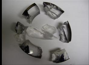
Example of shrapnel from catastrophic rupture
of rotor (acrylic) run at greater than
maximum safe design speed ( 14,500 rpm; 1518 rad/sec) This design flaw caused serious injury to operator.
0061. When operated at sonic speed,
the flow may emit a high pitched intense noise which can be damaging to the
hearing. Protective earphones can dampen
the high noise level. The noise level
can also be reduced by insulation and by
operating at slightly less than the optimum power or sonic speed.
Design Steps
1. Select desired mass
flow / or select desired cone inlet
diameter for average inlet wind speed expected.
For example, mass flow = 0.08 kg/s / or select cone
inlet of 13 cm to pass
expected wind speed of 5 m/s.
2. Calculate throat diameter needed to pass selected
mass flow rate; for example: m-dot (ρVA)
= 0.8 kg/s
Therefore if (ρ = 1.2 kg/m3 and A ( for diameter 13 cm) = 1.33 x 10⁻²
m2) then V inlet = 5 m/s.
3. Calculate throat
power available: P = ½ x (ρ
V A) x 3132 = ½ x 0.089 x 3132
= 3919 watts
4. Fabricate nozzles and throat to above specifications. That is,
Din = 13 cm., Dthroat = 2.07 cm . This will pass 5
m/s wind at sonic speed and 3919 watts of throat power. Higher inlet wind speeds will yield proportionately higher
potential power output.
Isentropic
Cone Motor
Design
Specifications for New Smaller Cones
(Cone Diameter 13 cm. )
(May 24/11)
Specifications
Inlet Diameter Di = 13 cm.
= 0.13 m
Inlet Area Ai = 1.33 x 10⁻² m2
Inlet Density ρ = 1.2
kg/m3
Therefore,
for Vi
= 5 m/s, mass flow rate m-dot = (ρ V A )I = 1.2 x 5 x
1.33 x 102 = 0.08 kg/s
Throat Area: A*.
( ρVA)* = 0.08, so A* = (
ρVA)* / ρ* V* = 0.08/
313 x 1.2 x .63394 = 3.36 x 10⁻⁴ m2 , and
Throat Diameter
: D* =
[3.36.x 10-4 /π]1/2 x 2 = .02068 m = 2.07 cm.
Throat Power = ½ m -dot 3132 = 3919 watts at Vi = 5 m/s (
18 km/hr)
7838 “ 10 m/s ( 36 km/h)
11,757 “ 15 m/s ( 54 km/h)
15,678 “ 20 m/s (72 km/h)
V Δp p/pe m-dot ‘Overdesign factor’ ThroatPower Take-off Power
( m -dot = 0.074 = 0.056 kg/s
)
5 m/s
15 Pa .0001481 0.08 x 1.08 x 1.425 3919 watts
10 60 .0005923 0.1596 x 2.157 x 2.85 7832
15 135 .01333 0.2394 x 3.24 x 4.275 11,757
20 240 .09872 0.3192 x 4.31 x 5.7 15.671
REFERENCES
1. Fales, E.N.,
“Windmills”. Sect. 9-8 in Standard
Handbook for Mechanical Engineers, Editors, Baumeister, T and Marks,
L.S.,
2. Munson, Bruce R., Young, Donald F., and Okiishi, Theodore, H., Fundamentals of Fluid Mechanics, John Wiley & Sons, New York. 1990.
3. Shapiro, Ascher, H., The Dynamics and Thermodynamics of Compressible Fluid Flow, 2 Vols., John Wiley & Sons, New York.1954.
4. R. Courant and K.O. Friedrichs, Supersonic
Flow and Shock Waves. Interscience,
5. This power take-off rotor means
is described in the disclosure of U.S. Utility Patent Application entitled:
“Method and apparatus for
efficiently generating and extracting power from an air flow to do useful work
“ . Applicant and Sole Inventor:
Bernard A. Power. Application No. 12/927,830. Filing Date
6. Machinery’s Handbook , 27th edition. Industrial Press, Inc.,
Converging/Diverging Cone Motor Accelerator Section (1,2) ( Rotor/ Power Take-off Section (5)) not
shown)
![]() Copyright Bernard A. Power , May 2011
Copyright Bernard A. Power , May 2011
Section Links:
Section 1: Linear ( streamline) Flow and Flow Power
Amplification
Section 2: Invention
No.1: A New Isentropic Air Motor and
Clean Energy Source
Section 5: A Note on
Isentropic Flow ‘Potential Motion’